
Hackaday Badge Quick Start
Tools home
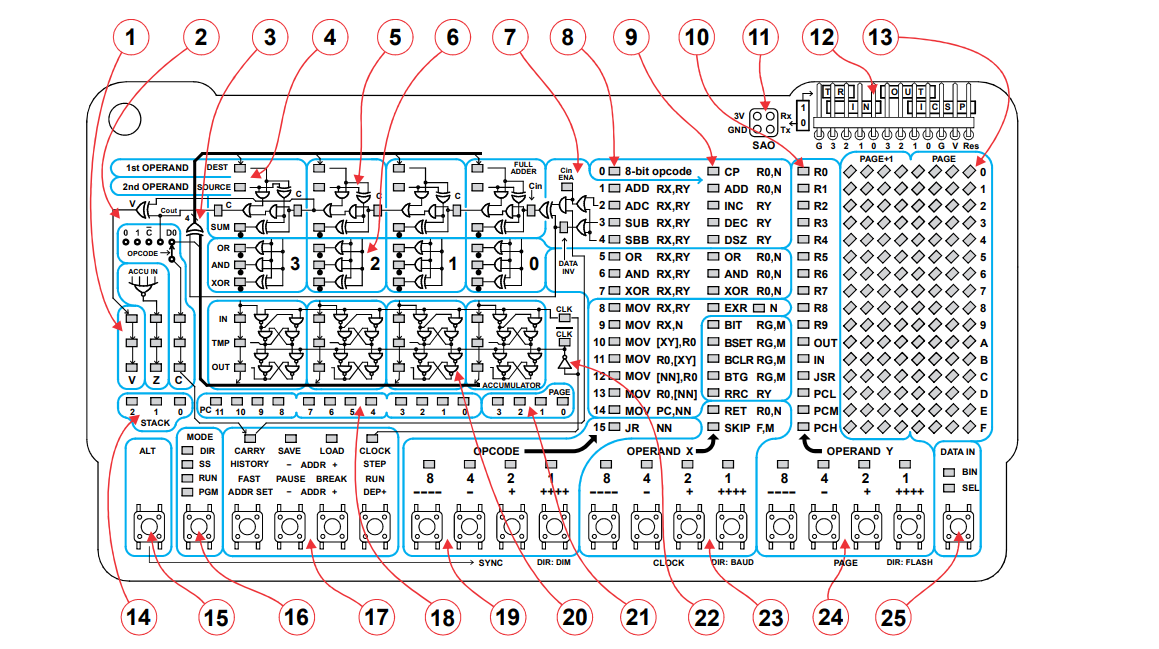
This year's badge is a complete CPU that you can peek inside! Let's get started. Refer to the picture to help identify the different parts (note: not all parts are discussed in this document).
Orientation
===========
On one side of the board there are two AA battery holders. Of course, you put the batteries in with the negative side towards the springs. If you don't get lights, press the On/Off button located between the batteries.
On the same side of the board, you'll see our CPU's instruction set. There are 16 primary instructions 0-F. Instruction 0 adds another 16 extended instructions. You can see the instruction table on the left of the board. To the right is the register structure. We'll talk about all of this later.
The Other Side
==============
On the other side of the board (the one in the picture) you'll see an array of buttons and LEDs. The 19 buttons are in groups:
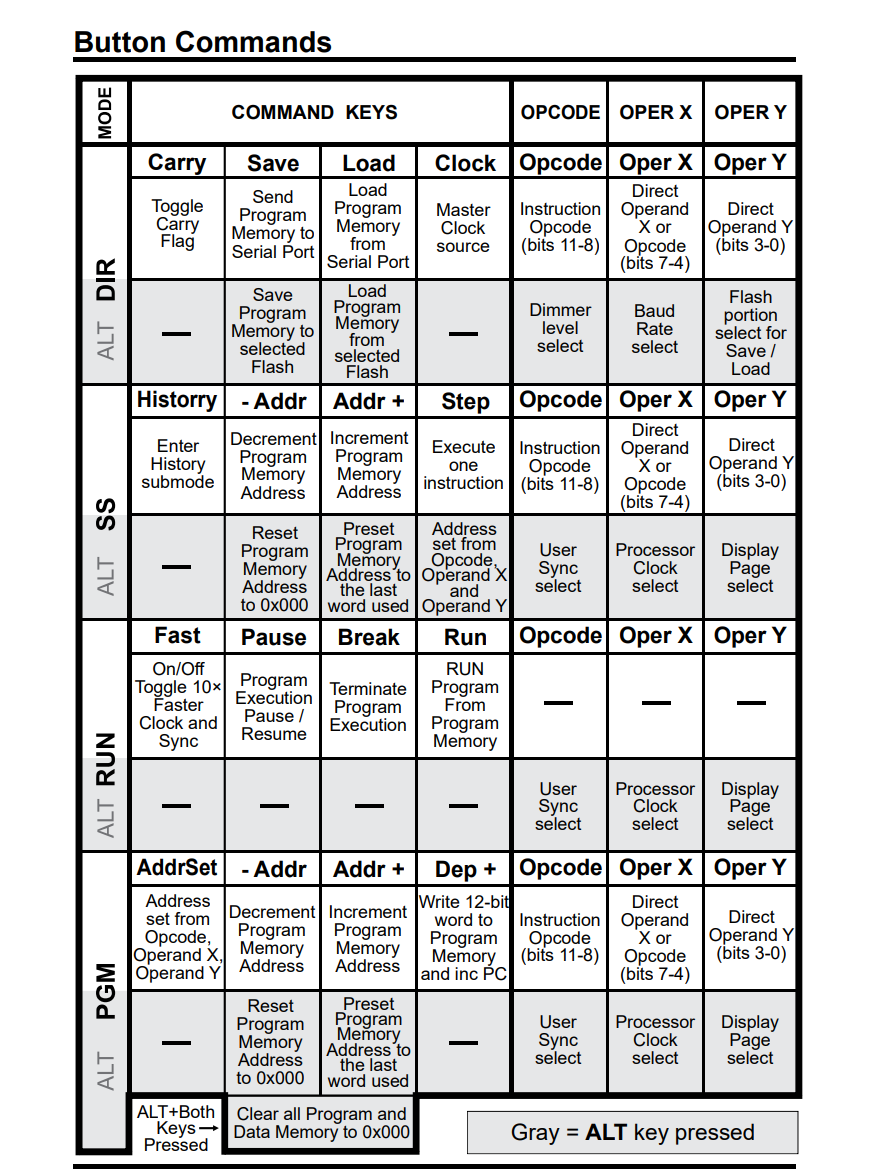
* The leftmost button [15] is the Alt button. You can see the Alt functions of each button written on the bottom of the PCB.
* The next button [16] selects the mode.
* The next four buttons [17] ]16= have specific functions based on the mode.
* The next four switches [19] set the opcode.
* The next eight switches [23,24] set the X and Y operand for each instruction.
* The final button [25] allows you to select the input mode.
The buttons for entering opcodes, X, and Y [19, 23, 24] are not in binary unless the BIN light is on over Button 25. Press the button to cycle between BIN and SEL.
In SEL mode, note above each switch in these groups there is a legend:
* \-\-\-\- - Subtract 4 from field (stop at 0)
* \- - Subtract 1 from field
* \+ - Add 1 to field
* \+\+\+\+ - Add 4 to field (stop at F)
LEDs
============
The LEDs above the buttons show the data entry, but you can also see the entry in the right hand array of LEDs [8, 9, 10]. The LEDs with instructions next to them [8, 9] show the opcode and X argument (which is also an opcode if the main opcode is 0). The third column of LEDs [10] shows the Y operand.
The LEDs in an array to the far right [13] show parts of the memory based on a page. This includes registers and special function registers.
You can ignore most of the internal LEDs for now, but you should find the PC [18] and page [21] LEDs (16 LEDs above the lefthand buttons). This will show you what address you are working with (PC is program counter).
Programmer's Model
==================
The CPU has a PC that address 4K of instruction memory. There are also 256 nibbles (4-bits) of data memory organized in 16 pages of 16. The first 10 registers are for general use (R0-R9). Registers A-F are special function registers.
Registers 10-1F are reserved for the call stack, allowing 5 levels of subroutines.
Registers E0-EF can act as fast storage for the main registers. The EXR instruction can swap registers starting a 0 with registers starting at E0. You can select how many registers are exchanged.
Because you need 12-bits of address, the jump and subroutines work a bit differently. Special function registers 0D, 0E, and 0F act as a single 12-bit register along with the JSR register (0C). See the manual for more about jumps. However, for this document we will only use the JR instruction which adds a signed 8-bit value to the PC. This allows you jump backwards or forwards a small amount.
To learn more about the various registers and instructions, see the full manual.
Program Input
=============
Armed with a knowledge of what registers are in use and which are available, and referring to the instructions set printed on the board, you can enter some simple programs. For example, let's enter MOV R0,#A (that is, put hex A into R0):
1. Optional: You may want to reset everything to a known state. To do this, start with the badge on and press ALT+SAVE+LOAD [15, 17] and hold all three keys. This document assumes you have PC=0 and PAGE=0
2. With or without a reset, press the 2nd button [16] until the PGM LED above it is lit. This puts you in program mode. Then press Opcode:8 (repeat until the LEDs at [19] are all off to clear the opcode), Opcode:1, Opcode:1 (set opcode to 8), and then Opcode:2 (add 1). Now the OPCODE LEDs [19] should be 1001 (9) and the left-most column of LEDs [8] should have 9 MOV RX,N lit up. If not, make adjustments until the LEDS are correct.
3. Next we need X [23] to equal 0 so press Operand X:8 until there are no LEDs over Operand X (8,4,2, or 1). If there are already no LEDs lit, you can skip this step.
4. Finally, we want Y [24] to equal A, so press Operand Y:1 twice followed by Operand Y:2 twice.
This is how you'd enter it in SEL mode (the final button on the right). If you press that button and select BIN, you can enter everything directly:
1001 0000 1010
5. Either way, you now need to write this to program memory. You do this using the 6th button from the left [17/DEP+]. Note that with PGM [16] lit up, the label above that button is DEP+ which is deposit and add 1 to the current location. You can see that the PC LEDs [18] are now lit to read 000000000001.
6. Now repeat the steps to enter: 1001 0001 0010 ( MOV R1, #2)
7. After depositing that instruction add another instruction: 0001 0000 0001 ( ADD R0, R1)
8. Finally, add: 1111 1111 1110 (JR #-2)
So our final program looks like this:
```
start: MOV R0, #$A
MOV R1, #2
loop: ADD R0, R1
JR loop
```
To run the program press the mode switch [16] until RUN lights up. Then follow the line of text that has the RUN led lit up next to it to the right. The final control button [17/RUN] has RUN on that same line. Press that button to start program execution. Press the button to the left [17/BREAK] to stop execution.
Note that the R0 LEDs near the top right [13] will count by twos and the R1 LEDs under that will have a binary 0010 (2) in them. The program counter (PC [18]) will cycle from 0 to 4 quickly.
You can press BREAK [17/BREAK] to stop the program. If you then change the mode button [16] to SS you can adjust the start address with ADDR + and - then use STEP [17/STEP] to see the program run an instruction at a time. If you want to reset before you start stepping, press and hold ALT+Save [15, 17/SAVE].
Reference Summary
=================
Don't Stop Now!
===============
Once you've entered a simple program, run it, and single stepped it, you are ready to tackle something more challenging. Look for more tutorials in this same folder.